
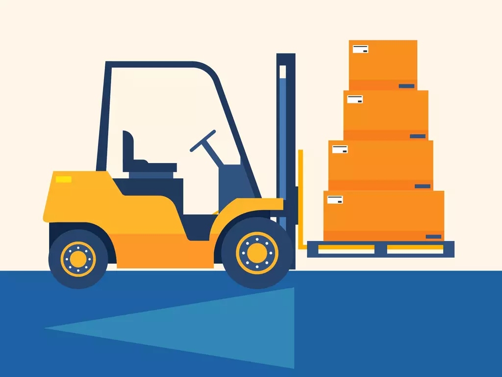
what is the combined center of gravity on a forklift
The combined center of gravity on a forklift is the single point where the entire weight of the truck and its load is concentrated, determining stability, tipping risk, and safe load capacity. This dynamic balance point shifts with every movement, lift, and turn, making it the most critical safety concept in material handling operations.
Understanding the Combined Center of Gravity
Every object has a center of gravity (CG)—the point where its weight is evenly distributed in all directions. For a forklift, this is not a fixed point. Instead, the combined center of gravity is the resultant balance point of three separate CG components: the forklift body itself, the load on the forks, and any additional forces from counterweight or mast movement. As these components shift during operation, the combined CG moves within a defined stability triangle or quadrilateral.
The Stability Triangle Concept
The safe operational envelope of a forklift is often visualized as a triangle formed by the two front drive wheels and the center of the rear steer axle. When the combined center of gravity falls inside this triangle, the forklift is stable. When it crosses the boundary, the truck will tip forward or sideways. The position of the combined CG is influenced by:
- Load weight and distribution – heavier loads and loads shifted forward move the CG toward the front axle.
- Mast tilt – tilting the mast backward moves the CG closer to the rear, improving stability; tilting forward moves it dangerously forward.
- Fork height – raising the load raises the combined CG, making lateral tip-overs more likely during turns.
- Counterweight mass – the rear counterweight is designed to offset forward shifts, but it cannot overcome gross overloads.
Why the Combined CG Difference from Static CG Matters
Unlike a static object where the CG is fixed, a forklift’s combined CG changes constantly. For example, when you drive with an empty pallet, the CG sits low and near the center. But when you lift a 2,000 kg load to full height, the CG rises significantly and moves forward. This is why the rated capacity plate on a forklift only applies at a specific load center (usually 500 mm from the fork face) and at a specified mast height. Every inch of load shift or elevation change directly alters the combined CG.
Forward Tip vs. Lateral Tip
Two primary tip-over scenarios exist. Forward tipping occurs when the combined CG moves beyond the front axle line—usually from overloading or driving with a heavy load and a tilted-forward mast. Lateral tipping occurs when the CG moves outside the side boundary of the stability triangle, often during sharp turns at speed with a raised load. The height of the combined CG is the main variable: the higher it is, the smaller the lateral stability margin.
Practical Calculations and Load Center
Forklift engineers calculate the combined CG using vector mathematics. For a typical counterbalanced truck, the formula accounts for the truck’s own mass, the load mass, and the distances from a reference point (usually the front axle center). The moment equation is:
Total moment = (Truck weight × truck CG distance) + (Load weight × load CG distance)
Then divide by total weight to find the combined CG distance from the front axle. This is why a load center longer than the rated distance (e.g., 600 mm instead of 500 mm) reduces capacity—the load’s moment arm increases, moving the combined CG forward beyond the permissible range.
Dynamic Effects: Acceleration, Braking, and Turning
Inertial forces add another layer to the combined CG. When a forklift accelerates, the load tends to remain behind the truck, momentarily shifting the combined CG rearward (increasing stability). During braking, the opposite occurs—the load pushes forward, shifting the CG forward and increasing tip risk. Turning creates centrifugal force that acts outward from the center of the turn, effectively moving the combined CG sideways. Expert operators always slow down before turning with a raised load because the lateral shift is unpredictable at speed.
How Manufacturers Design for Combined CG Stability
Counterbalanced forklift design is a careful exercise in placing mass. The battery (in electric trucks) or the engine (in IC trucks) plus the cast iron counterweight sits at the rear, far behind the front axle, creating a long lever arm. The mast and carriage are positioned near the front axle to minimize the load’s moment arm. The result is a machine that can handle heavy loads while staying within the stability triangle under normal conditions. However, aftermarket attachments (like side shifters or rotators) add extra weight forward and extend the load’s reach, altering the designed combined CG. Always consult the manufacturer before adding attachments.
Role of Stability Test Standards
International standards like ISO 1074 and ANSI/ITSDF B56.1 mandate specific stability tests that simulate driving, lifting, tiering, and traveling with different load heights. These tests verify that the combined CG never leaves the stability triangle under defined operating conditions. For instance, a common test places the maximum rated load at the rated load center and lifts it to the maximum fork height while the truck is on a 15% grade. Only if the combined CG remains inside the triangle does the truck pass. This is why you must never modify a forklift’s counterweight, tires, or mast—these changes invalidate the certified combined CG envelope.
Operator Training and the Combined CG
Most forklift accidents are not random—they occur when operators violate the stability triangle rules. Understanding the combined CG helps operators make better decisions: do not exceed the load capacity, keep load centers as short as possible, tilt the mast back when carrying, and always lower the load before turning. A highly effective training exercise is to place a marker on the floor showing the stability triangle and then have operators simulate different load scenarios to see where the combined CG would fall.
Temperature and Tire Pressure Effects
Even tire pressure influences the combined CG. Soft rear tires compress differently under load, slightly moving the rear axle’s effective center, which can shift the stability triangle boundary. Similarly, on uneven or soft ground, the triangle’s base becomes narrower, reducing the safe CG envelope. Always check tire pressure and floor conditions before operation.
Modern Solutions: Integrated Load Moment Indicators
Advanced electric and lithium-ion forklifts now feature load moment indicators (LMIs) that continuously calculate the combined center of gravity using sensors on the mast, carriage, and hydraulic pressure. These systems display real-time stability margins and can automatically reduce travel speed or alarm when approaching the tip-over threshold. If you are in the market for a high-tech forklift that prioritizes stability, the Liftron Material Handling lineup offers robust counterbalanced trucks with precise engineering.
For warehouse operations focused on energy efficiency and predictable performance, the Liftron DL SERIES integrates a low-mounted lithium battery that keeps the combined center of gravity lower than traditional lead-acid units, significantly improving lateral stability at high fork heights. This design choice directly addresses the primary instability condition—elevated loads—by reducing the vertical position of the combined CG.
Tables: Load Center vs. Capacity Example
| Load Center (mm) | Rated Capacity (kg) | Approx. CG shift from front axle (mm) |
|---|---|---|
| 400 | 1800 | + 30 (rearward) |
| 500 (standard) | 1500 | 0 (design point) |
| 600 | 1200 | – 45 (forward) |
| 700 | 1000 | – 95 (forward) |
The above table illustrates how a longer load center reduces capacity. Every operator and warehouse manager should memorize this relationship—it is the direct practical consequence of the combined center of gravity. When in doubt, always test a loaded truck on a stable, level surface with a slight tilt and check for rear wheel lift. If the rear wheels raise off the ground, the combined CG has crossed the front axis, and the load must be reduced immediately.
Final Safety Takeaway
Never assume that a forklift’s rated capacity is a fixed number. It is a conditional value that depends entirely on the combined center of gravity. By understanding how weight, distance, height, and motion interact, you can prevent the most common and fatal forklift accidents. Train your team annually, enforce load center rules, and choose equipment from reputable manufacturers that engineer stability from the ground up. Remember that the combined CG is not just a physics concept—it is a daily safety metric that deserves your full attention.
Add a review
Your email address will not be published. Required fields are marked *